NOZZLES
The world’s finest, most accurate precision made nozzle. Once the client buys these nozzles, they never buy any other. Truly a good product.
USGR considers these nozzles to be the most precise, highest quality, best designed efficient watering, misting, fogging, humidifying nozzles manufactures in the world. Available to commercial greenhouses only. Minimum order$0 USD; required orders of 30 to 50 Z, K, L; from 10 to 15 of G & T, 20 nozzles of B type.
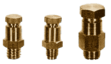
5/16″ – 24
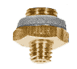
3/8″ c
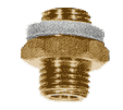
1/4″ m-pipe
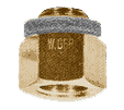
1/4″-f-pipe
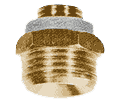
1/2″ m-pipe
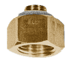
1/2″ f-pipe
HOW TO SELECT THE RIGHT NOZZLE
Find the nozzle most suitable for your particular application under “Type of spray”. Out of these, select a nozzle size that can cover the width of your area or bench to be watered or misted under “Recommended spacing”. If the largest available nozzle cannot cover your area in width, divide the area into two or more smaller sections lengthwise and plan to install two or more lines (pipes).
The values given under “Recommended spacing” can be altered a maximum of 10% either way, as long as the total sum of both values does not increase.
Example I: A size 10 nozzle with a recommended spacing of 34 by 44 inches may be installed from 30 by 48 inches to 38 by 40 inches. The total sum of both values remained 78. (34+ 44 = 78, 30 + 48 = 78, 38 + 40 = 78).
Example II (metric): A size 10 nozzle with a recommended spacing of 0.9 by 1.1 meters may be installed from 0.8 by 1.2 meters to 1.0 by 1.0 meters. The total sum of both values remained 2.0(0.9+1.1=2.0,0.8+1.2=2.0,1.0+1.0= 2.0).
These outstanding precision made brass nozzles from Europe priced as low as $0.00 USD. each to large maximum coverage nozzles priced at $0.00 USD each and up.
|
Nozzle
|
Discharge/minute
U.S.-Gal./Litre |
øCoverage
Feet/Meter |
Recommended spacing*
|
Type of spray and
|
||
| Type | Size | Inches | Meter | typical application | ||
| B | 4 | 0.045=0.17 | 2=0.60 | – | – | humidification |
| B | 6 | 0.09 = 0.34 | 4 = 1.25 | – | – | |
| B | 8 | 0.17 = 0.62 | 5-1 /4″” = 1.60 | 28 x 32 | 0.7 x 0.8 | |
| B, K, L | 10 | 0.2642 = 1.00 | 6-3/4″” = 2.05 | 34 x 44 | 0.9 x 1.1 | mist propagation |
| B, K, L | 12 | 0.36 = 1.37 | 7-3/4″” = 2.35 | 42 x 48 | 1.1 x 1.2 | |
| B, K, L | 15 | 0.54 = 2.03 | 9-1 /4″” = 2.80 | 46 x 60 | 1.2 x 1.5 | |
| B,K,L | 20 | 1.07=4.03 | 11=3.40 | 60×70 | 1.5×1.8 | misting-cooling |
| B, G | 25 | 1.50 = 5.66 | 15 = 4.60 | 78 x 96 | 2.0 x 2.4 | |
| B, G | 30 | 2.03=7.66 | 20=6.20 | 108×120 | 2.8×3.2 | |
| G. T | 40 | 3.7 = 14 | 27= 8.30 | 144 x 156 | 3.7 x 4.1 | cooling-irrigating |
| G, T | 50 | 6.2 = 23 | 32 = 9.60 | 168 x 192 | 4.3 x 5.0 | |
| T | 60 | 9.3=35 | 34=10.50 | 180×216 | 4.7×5.5 | |
| T | 80 | 13 = 50 | 41 = 12.50 | 216 x 264 | 5.6 x 6.8 | fine irrigation |
| T | 100 | 15 = 57 | 44 = 13.50 | 240 x 276 | 6.0 x 7.0 | |
| T | 150 | 19 = 70 | 46 = 14.00 | 240 x 276 | 6.0 x 7.0 | |
| Z2 | – | 0.81=3.1 | 13 = 3.90 | 60 x 96 | 1.5 x 2.4 | cooling-irrigating |
| Z3 | – | 1.19 = 4.5 | 15 = 4.50 | 72 x 108 | 1.8 x 2.7 | |
| Z6 | – | 2.51=9.5 | 22=6.80 | 108×156 | 2.7×4.0 | |
HOW MANY NOZZLES
To determine how many nozzles are needed to cover an area, divide the length of your area to be covered by the
- Nozzle types are identified by a single letter .
- Nozzle sizes are given in numbers representing the nozzle orifice in tenths of millimeters.
- Discharge/minute is the amount of liquid discharged (sprayed) through the nozzle orifice per minute, at a pressure of 36 PSI measured directly in front of the nozzle.
- øCoverage gives the diameter covered by a nozzle when mounted in an upright position 42″ (1.1 meters) above the top of a crop and with 36 PSI water pressure measured directly in front of the nozzle.
- “distance” value of the nozzle you have selected. If you have altered the spacing values to match the width, use the new distance value. Then round off upward or add one nozzle to each line to assure adequate coverage of the corners at each end.
- Example 111: A bench, 4 by 100 feet = 48 by 1200 inches, is to be misted with L12 nozzles. The recommended spacing for a size 12 nozzle is 42 by 48 inches which is suitable without alterations. The total number of nozzles required is 1200 divided by 42 = 28.57, rounded off to 29.
- Example IV (metric): A bench to be misted is 1.4 by 30 meters and L15 nozzles have been selected. The recommended spacing of a size 15 nozzle is 1.2 by 1.5 meters, changed to 1.3 by 1.4 meters to suit the application. Now divide 30 meters into 1.3 meters equals 23.08, rounded off to 24. The last (or first) nozzle’s distance from each end can be calculated by multiplying your (rounded off) number of nozzles with the same spacing value used to determine the number of nozzles needed. From it deduct the actual length of your bench or area. e.g. (to continue example III) 29 x 42 = 1218 less 1200 = 18 inches. The resulting figure, when deducted from one spacing value and then split in half, is the last (or first) nozzle’s distance from each end of the bench or area to be watered or misted. E.g. 42 less 18 = 24, half of it = 12 inches.
- *Recommended spacing: To cover a rectangular area or bench with circular nozzles requires some overlapping to eliminate dry spots.
The first figure in each column represents “distance between nozzles” on a pipe, with the required overlap to avoid dry spots. The second figure in each column represents the “width of coverage” for a certain area, bench or section. All values offered in this table are on the “conservative average” side and may be increased by 10 to 20% if an irrigation specialist custom designs the piping and pump layouts.
The unique environment conditions in greenhouses requires the use of specifically designed nozzles for humidifying, misting, cooling and irrigating. Pate nozzles are specifically engineered, accurately researched and carefully machined to fill this demand.
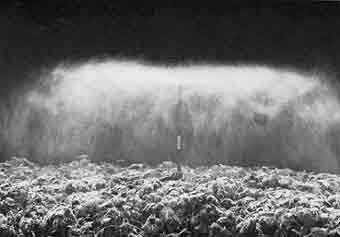
SPRAY CHARACTERISTICS
 As illustrated by the drawing, the spray is formed by a stream of water entering the nozzle and being accelerated by the cone shape of the chamber before it is ejected through the orifice at high speed. The deflector with its tip angled at 155- acts as a wedge, parting the stream from the centre outward, forcing it to form a flat disk of water. The droplets which are ejected from the edge of this disc are extremely small and carry a considerable charge of static electricity. The majority of these small droplets carry a negative charge, and any large droplets have a positive charge. The ratio of the two droplet sizes and their respective charges depends on the size of the nozzle orifice and the pressure.
The larger, positively charged droplets fall to the ground and leave the small negatively charged drops without the possibility of recombination. These small droplets are therefore forced to evaporate in the air. This causes high humidification at relatively low pressures, a purification of the air through the binding of dust particles to the droplets and cooling as evaporation consumes heat. These droplets absorb approximately five times the oxygen normally contained in water as they travel through the air. If the system is being used for irrigation, this additional oxygen penetrates the soil with the droplets and gives increased aeration.
NOZZLE DESIGN
The deflector (repellent) is located directly in the path of the discharge stream, deflecting it into a horizontal circular spray at a right angle to the orifice. The machined deflector has a 155- coned tip which gives the nozzle a larger coverage and keeps the tip surface free of small particles for perfectly even coverage at all times.
The orifice discharges a laminar flowing stream of liquid to insure even coverage. A tapered compression chamber increases the speed of liquid flowing through the orifice, thus producing a spray of the finest possible atomization at relatively low pressures (20 to 40 PSI). The result is less clogging, less wear, long lasting original performance, elimination of high pressure equipment, lower maintenance cost, and fewer breakdowns if any.
Any particles smaller than the nozzle orifice are able to pass freely through the system without clogging, since there are no internal obstructions to the flow.
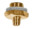
FILTERS
One of the biggest problems in mist, fog and irrigation nozzles is if there is poor water quality, it plugs the line and the nozzle, particularly corrosive to plastic nozzles, not so much with our brass. If installing these high quality nozzles, use a good 100 mesh line strainer and clean the filters often.