Sizing and Selection of Equipment
There are many factors contributing to the need for greenhouse cooling and ventilation equipment. The primary source of heat in a greenhouse is solar radiation. To reduce greenhouse temperatures, air removal is required and its rate of removal is a function of the floor area. A simplified method for sizing and selecting equipment for greenhouse temperature control is included in this brochure.
| feet | Under 1000 | 1000 | 2000 | 3000 | 4000 | 5000 | 6000 | 7000 | 8000 |
|---|---|---|---|---|---|---|---|---|---|
| F Elev(e) | 1 | 1.04 | 1.08 | 1.12 | 1.16 | 1.2 | 1.25 | t30 | 1.36 |
| FC | 5000 | 5500 | 6000 | 6500 | 6000 | 7500 | 8000 | 9,000 | 10,000 |
|---|---|---|---|---|---|---|---|---|---|
| F Light(I) | 1 | 1.1 | 1.2 | 1.3 | 1.4 | 1.5 | 1.6 | 1.8 | 2 |
| °F | 18 | 17 | 16 | 15 | 14 | 13 | 12 | 11 | 10 | 9 |
|---|---|---|---|---|---|---|---|---|---|---|
| F Winter(w) | .83 | .88 | 0.94 | 1 | 1.07 | 1.15 | 1.25 | 1.37 | 1.5 | 1.67 |
| °F | 10 | 9 | 8 | 7 | 6 | 5 | 4 |
|---|---|---|---|---|---|---|---|
| F Temp (t) | 0.7 | 0.78 | 0.88 | 1 | 1.17 | 1.4 | 1.75 |
| feet | 20 | 25 | 30 | 35 | 40 | 45 | 50 | 55 |
|---|---|---|---|---|---|---|---|---|
| F Vel (v) | 224 | 2 | 1.83 | 1.69 | 1.58 | 1.49 | 1.41 | 1.35 |
| feet | 60 | 65 | 70 | 75 | 80 | 85 | 90 | 95 | 100 |
|---|---|---|---|---|---|---|---|---|---|
| F Vel (v) | 129 | 1.24 | 1.2 | 1.15 | 1.12 | 1.08 | 1.05 | 1.02 | 1 |
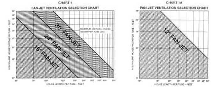
SELECTING ACME FAN-JET:
From charts 1 and 1A, locate the greenhouse size using the “equivalent width” from the formula below nd the actual length of the greenhouse.
ACTUAL WIDTH x Fe x F1 X Fw = (EQUIVALENT WIDTH)
DO NOT EXCEED 30′ IN ACTUAL HOUSE WIDTH WITH ONE FAN-JET.
Select the Fan-Jet(s) within the range shown. If the Fan-Jet is to be used for distributing heat, include the heat accessory kit to go with the Fan-Jet. Select the proper model of tubing according to the length of the greenhouse. Improper tube punching will not provide uniform air distribution.
SELECTING ACME EXHAUST FANS:
Winter Ventilation: (used in conjunction with Fan-Jet) Between 1 1/2 and 2 CFM per square foot of floor area is required for winter ventilation.
LENGTH X WIDTH x 2 x Fe x F1 x Fw = WINTER CFM
DO NOT EXCEED THE CAPACITY OF THE FAN-JET WITH EXHAUST.
Either increase the size of the Fan-Jet or reduce exhaust below the Fan-Jet CFM rating.
Summer Ventilation and Cooling: Approximately 8 CFM per square foot of floor area is required for maximum ventilation and cooling.
LENGTH X WIDTH x 8 x Fe x F, x Ft = SUMMER CFM.
If fans and pads are less than 100 feet apart, adjustments must be made for air velocity.
LENGTH X WIDTH x 8 x Fv = CFM FOR SUMMER.
Select the exhaust fans to provide the higher of either CFM for conditions or CFM for velocity.
SELECTING ACME KOOL-CEL SIZE:
Kool-Cel is most efficient with air velocity of 250 fpm. Therefore, for maximum efficiency add the total exhaust selected and divide by 250 to get the square feet of pad required. Divide the square feet of pad by the available length of run to get the height of Kool-Cel required. Round off to the nearest foot.
The pads are 4″ x 12″ x 24″, 36″, 48″, 60″ & 72″. Using the tall pad support, they may be stacked to provide 60″, 72″, 84″, and 96″ high pads, The number of Kool-Cel pads required is equal to the length of run.
Select the distribution system that matches the length of run up to 100′. (50′ in PDR systems.)
Select the water pump according to the length of the distribution system. Use #15 pump for systems up to 40′, #30 up to 70′, and #60 up to 100′.
SELECTING INLET SIZES:
Winter Ventilation: The inlet shutter sizes for Fan-Jet systems are listed with the Fan-Jets on Page 10.
Summer Ventilation and Cooling: The inlet area for Kool-Cel pads should be continuous and at least 2/3 of the pad height. In no case should the velocity of air inlet for summer cooling or ventilation exceed 400 fpm. Divide total CFM by 400 to get square feet of inlet required. Select inlet shutters using the opening area shown on the inlet shutter chart. (Page 9).
CONTROLS
Because of non-resident management of greenhouse operations today, automatic controls become a necessity.
If simple one or two step heating or cooling is required, thermostats will satisfactorily operate the equipment. But to conserve energy, staging equipment is recommended to use minimum equipment while achieving desired temperatures.
The ACC-I has zero, one, two, or three stages of heat, one stage of circulation and four, five, six, or seven cooling/ventilation stages.
The Grotron II has two stages of heat, one for circulation and five stages of cooling/ventilation. More features are a part of the Grotron II system and are detailed on Page 19 and in Brochure C46.
Both Grotron II and ACC-I are low voltage (24 volts) controllers and require 24 volt control relays. Select one PB90ER24-1 relay for each piece of equipment and one PB90ER24-1 and PB90ER24-2 relay for each two speed or two directional motor. (Inlet shutters may be grouped and operated with one relay.)
Typical Example:
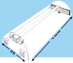 A 25′ x 100′ greenhouse located in an area with less than 1000 feet elevation and 5000 f.c. of light. This example is based on 15 degree winter inside temperature above outside temperature and 7 degree rise from pad to fan in summer. Air flow will be end to end and, therefore, fan to pad distance is 100′.
| CALCULATIONS | EQUIPMENT SELECTION |
|---|---|
| Fan-Jet | |
| Actual Width x Fe x Flx F w = (Equivalent Width) 25′ x 1.0x 1.0x 1.0 = 25′ (25′ is less than 30′; therefore, one unit is OK) |
1-RCA24F from chart #1; WAAC333MT from page 10 performance data; 100 feet 24″ tube punched “BP” from page 11. Tube Selection Chart; 1-100′ support package; 13 hangers and rings (100′ / 8 = 13); 24″ heat accessory if heat is to be distributed by the Fan-Jet. |
| Exhaust Fans | |
| Winter: L x W x 2 x Fe x Fix Fw = CFM 100 x 25 x 2 x 1.0 x 1.0 x 1.0 = 5,000 CFMSummer: L x W x 8 x Fe X Fl x Fl= CFM 100 x 25 x 8 x 1.0 x 1.0 x 1.0 =20,000 CFM |
2-DCA36G fans at .05″ SP =11,065 CFM each; one is 2 speed, (low speed for winter ventilation); therefore select 1-DCA36G and 1-DCA36G-2S each with slant wall housing, shutter and guard. (Note 2 spd. Max. = 10,055 CFM); (Total CFM = 11065 + 10,055 21,120) |
| Kool-Cel System | |
| 21,120 CFM / 250 = 84.48 sq. ft. 85 / 20 (length of pad) = 4.25 (use 48″) |
20 – 48″ Kool-Cel pads 1 – 20′ Distribution and Retum System 1 – # 15S Pump 1 – Plumbing Package |
| Inlet Shutters | |
| Winter Summer21,120 / 400 = 52.8 sq. ft. 4 x 15.4 = 61.6 sq. ft. 4 |
See Fan-Jet Above A balance of both pad height and length of run is required.- WAAC6340MT @ 15.4 sq. ft. each |
| Controls | |
| Automatic operations required One relay per each piece of equipment
|
1 – Grotron II or ACC-1 9 – Relay PB90ER24-2 |